Maker's Guide
Custom Phone Stand
A step-by-step guide to modeling, extruding, and adding a vector design in FreeCAD
Maker's Guide
A step-by-step guide to modeling, extruding, and adding a vector design in FreeCAD
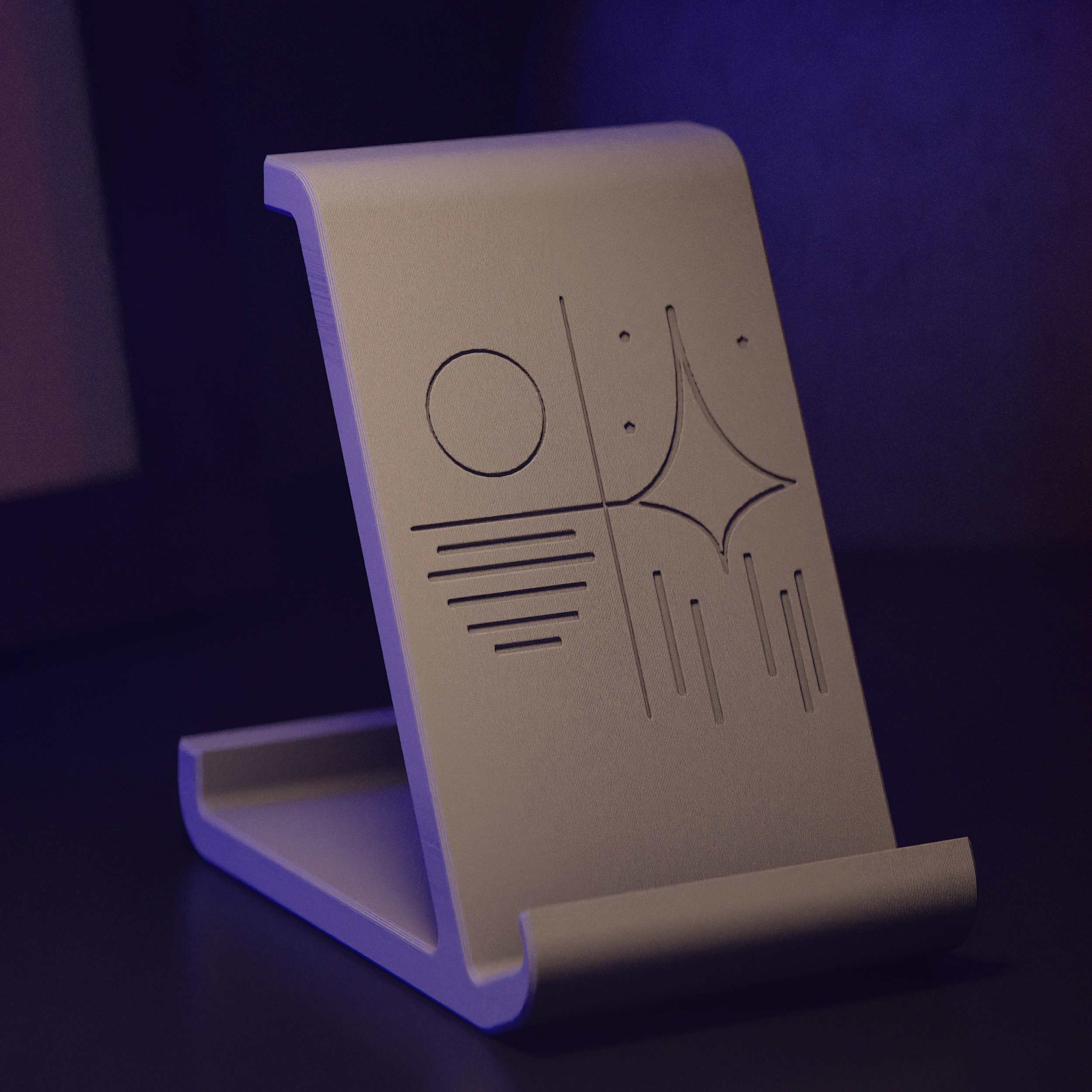
Today's project is a quick and functional one: designing a phone stand in FreeCAD. While this may seem simple, it introduces useful techniques like path-based extrusion and importing custom vector artwork into your part. It's an ideal project if you want to get comfortable with core modeling concepts while also adding a layer of personalization. The idea came from a need to keep my phone upright and within reach at my desk. I already had a version made, but in this guide, I show you how to build a new shape and embed a custom vector graphic onto its face.
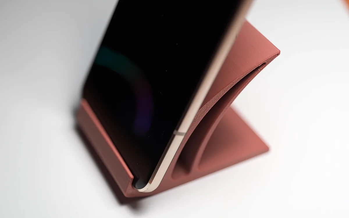
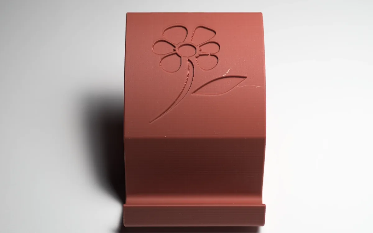
Vector design of a flower was created in Inkscape and imported as .DXF
Before jumping into CAD, I took a few key measurements of my phone: • Phone thickness with case: 13 mm • Phone height: ~170 mm These rough values help define the channel that will hold the phone and the overall stand dimensions. Adjust your model according to your device. If use the a phone case, measure your phone with the case attached.
Almost forgot! Here is a quick guide to help find feature tools used in the following steps.
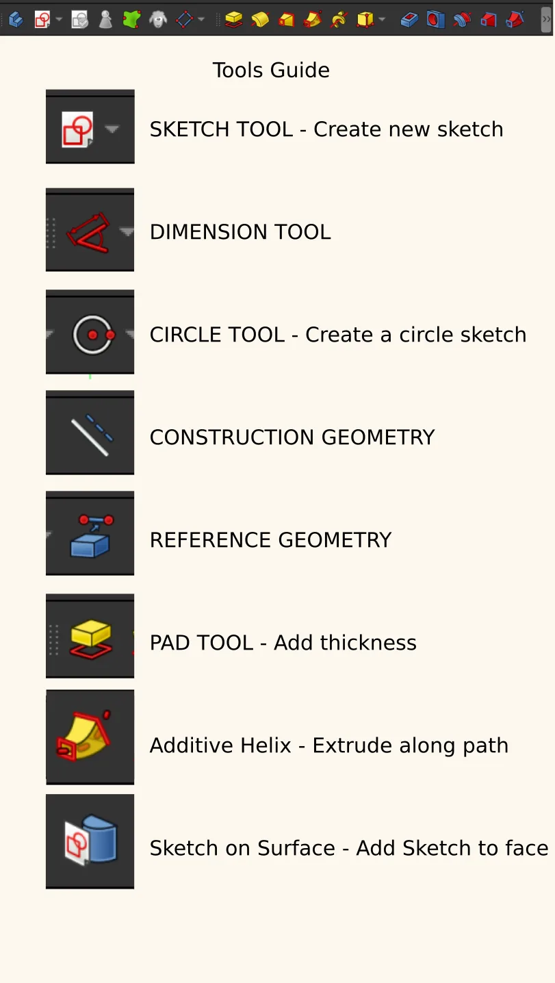
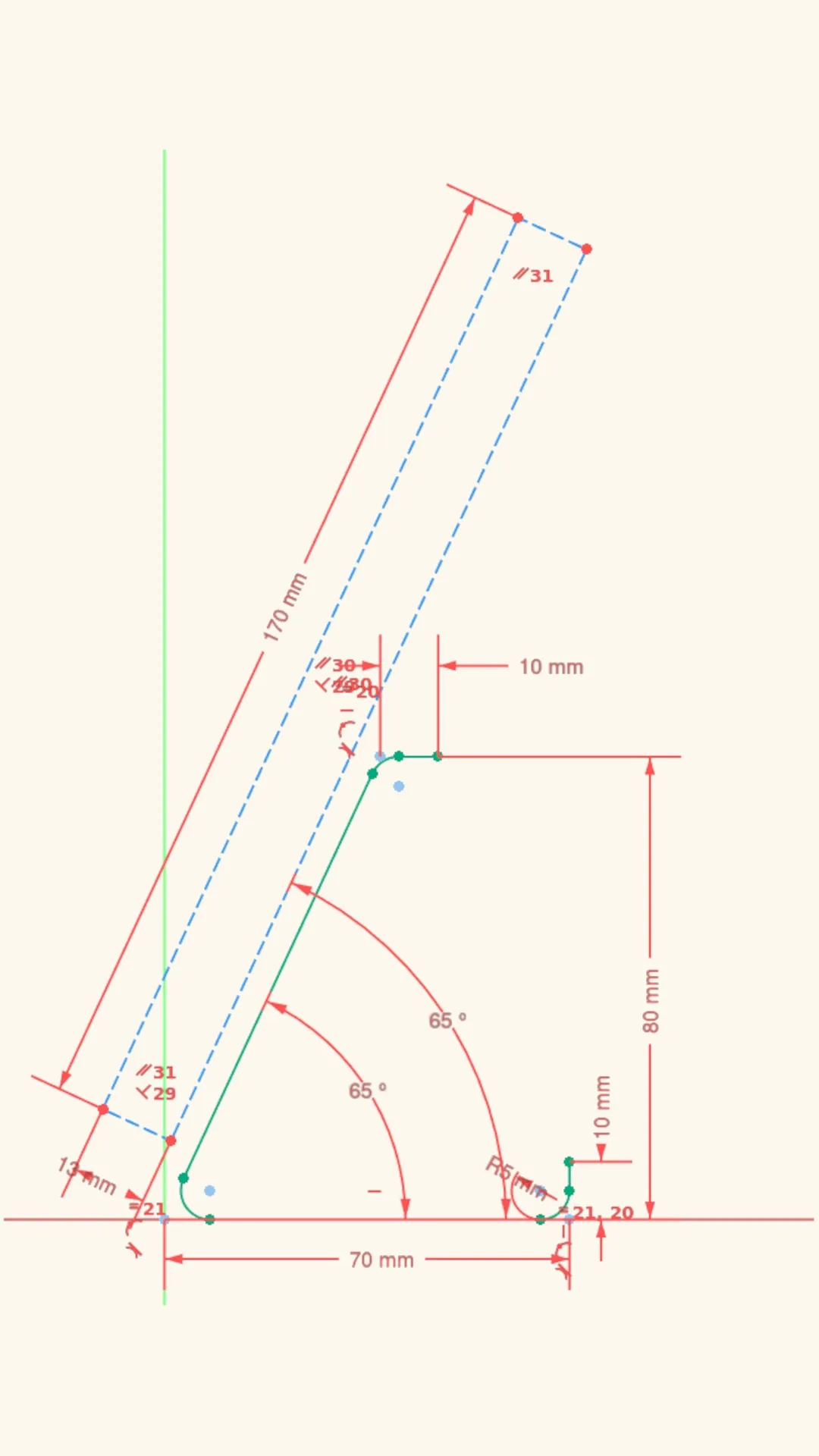
In FreeCAD, I began with a sketch on the front plane. I started with a construction rectangle representing the phone in profile, then rotated it to match a viewing angle of 65 degrees from horizontal. This gives a nice backward tilt for readability and balance. Once the reference phone sketch was in place, I created a polyline profile for the stand itself—a simple, angular shape with a few filleted corners for a clean aesthetic. • Overall width: 70 mm • Depth: 10 mm • Front height: 80 mm • Fillet radius on corners: 5 mm This shape became the guide path for the next step.
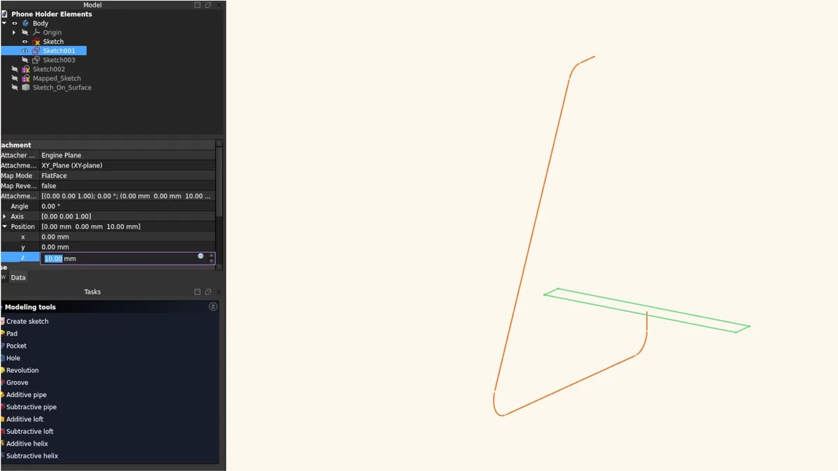
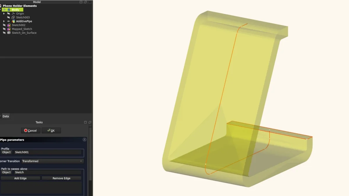
On the top plane, I created a centered rectangle: 6 mm tall, 55 mm wide. This would form the cross-section of the extrusion. NOTE: I used a 10 mm Z-offset for alignment and a wireframe view for clarity during setup. Then I used the Additive Pipe tool to sweep the rectangle along the profile path created earlier. This forms the core shape of the stand.
To hold the phone in place, I needed a small lip. I created a second sketch on the front plane, using external geometry from the existing model for alignment. This sketch formed a small L-shaped bracket at the bottom: • Lip height: 5 mm • Channel depth for phone: 13 mm • Wall thickness: 6 mm and taper to 2mm Once sketched, I extruded this section symmetric to plane to match the main stand body.
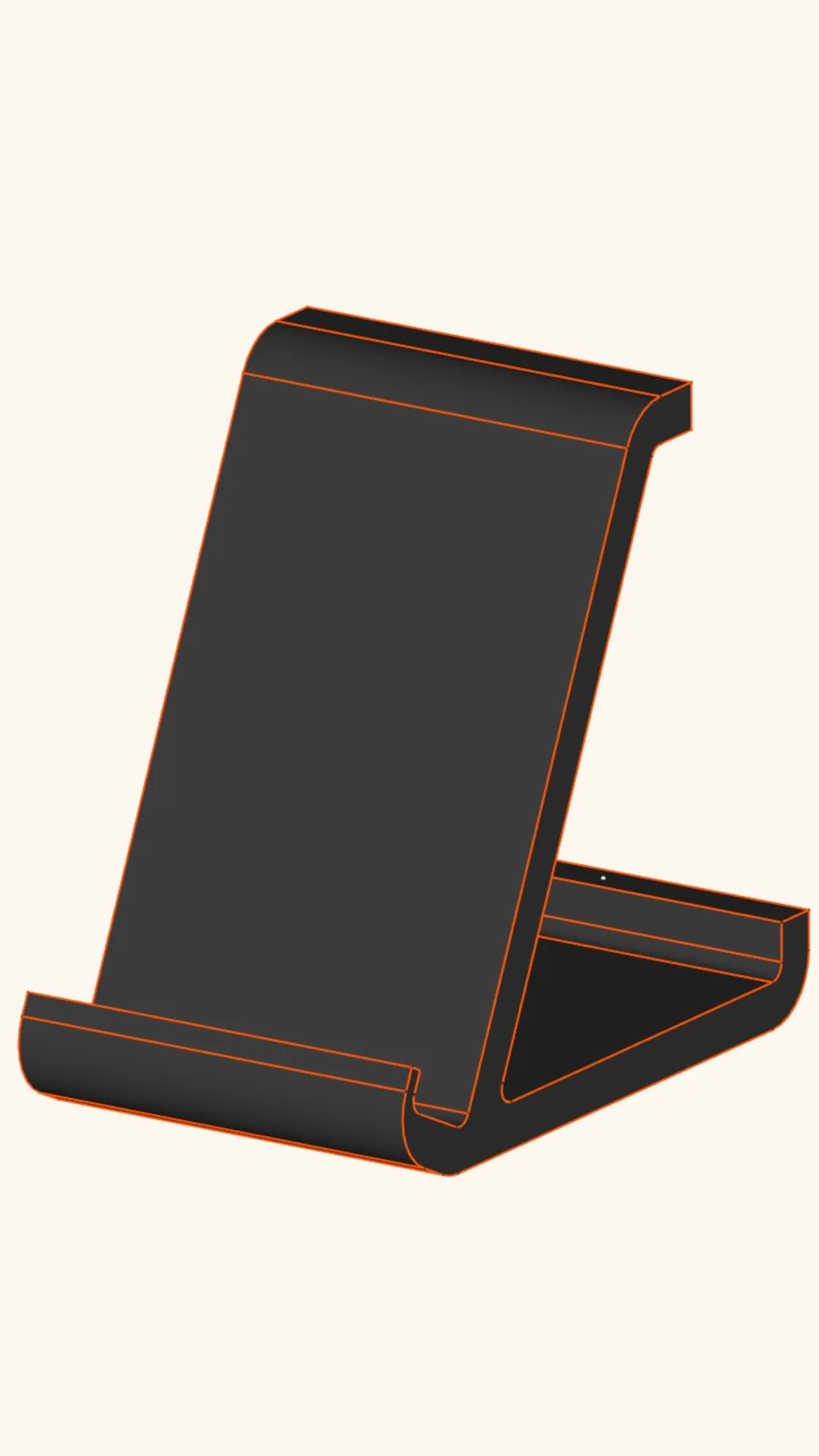
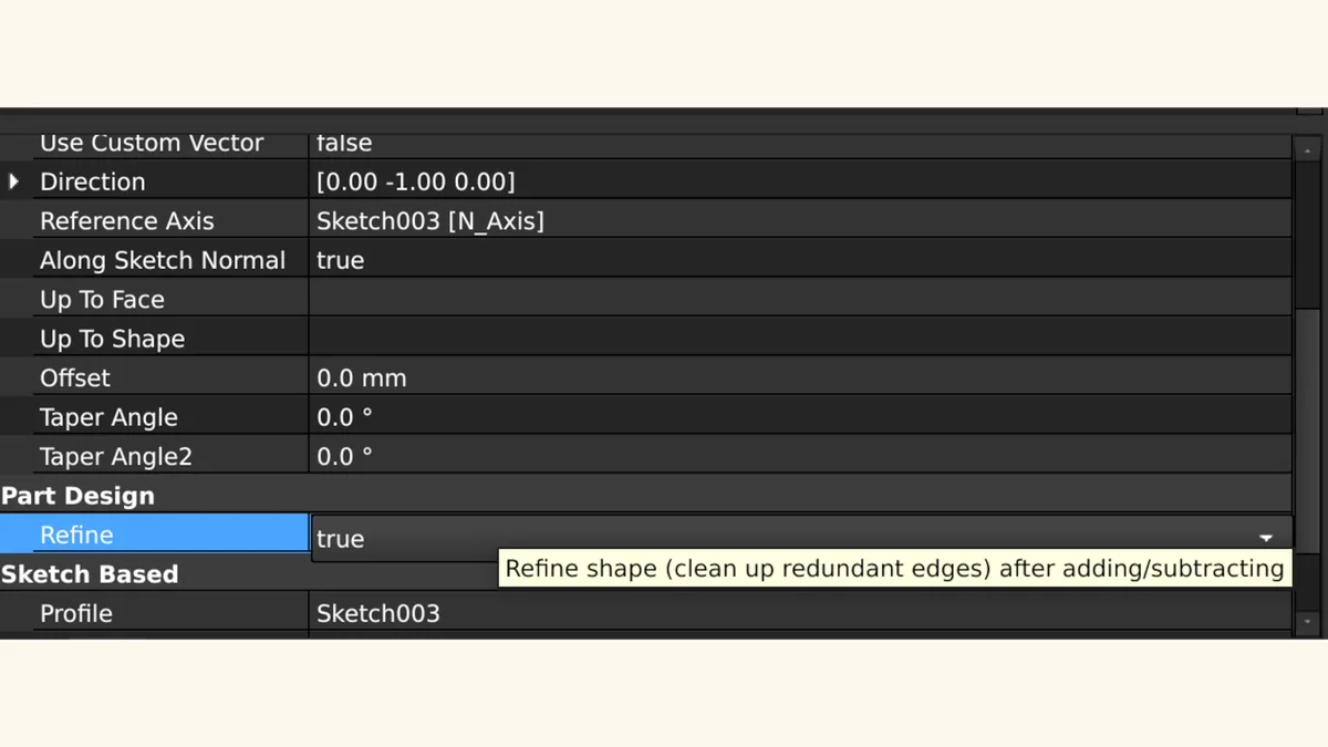
There was a small visual artifact where the two bodies intersected. To clean this up, I enabled Part Design Refine = True, which merges the geometry into one seamless solid. Then, I added a chamfer to the top edge of the face, sized at 0.7 mm.
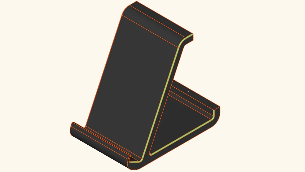
At this point, the 3D model can be 3D-printed and used as a phone stand. If you want to learn how to customize it using vector based sketches, keep reading.
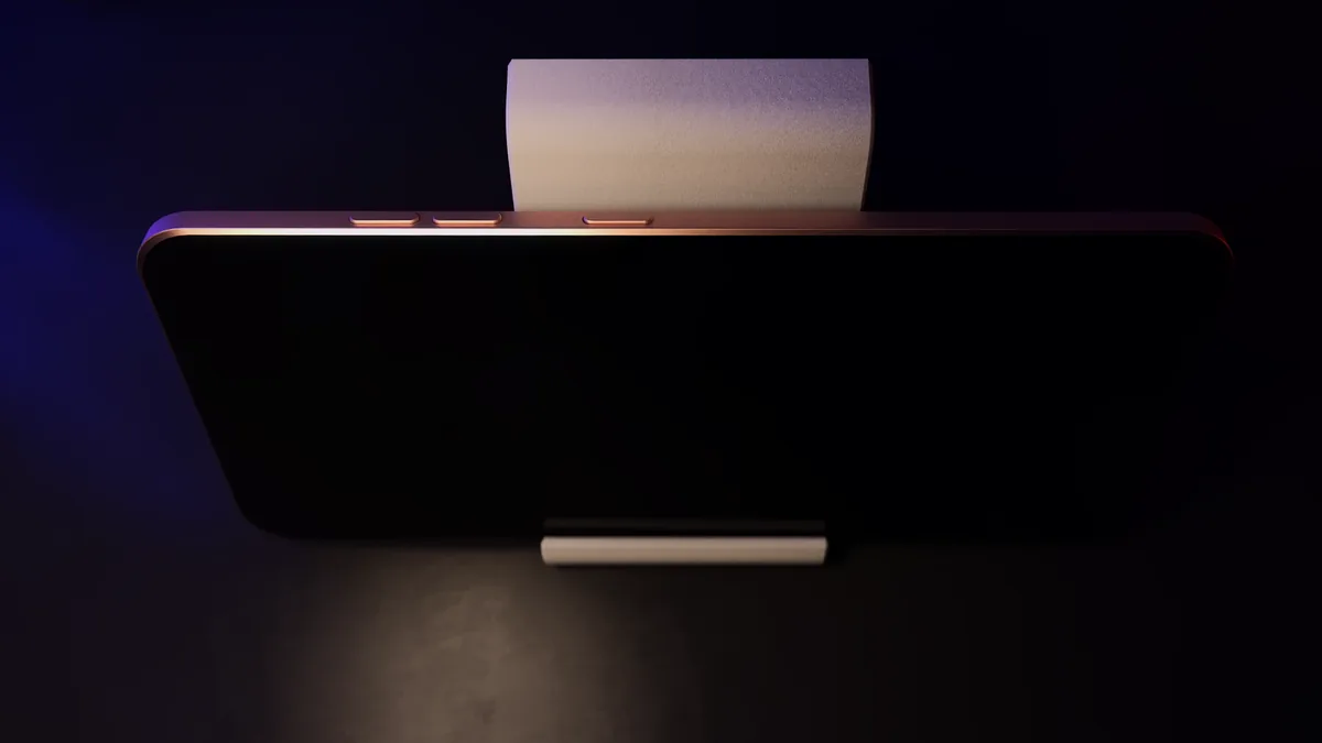
Rendered in Blender
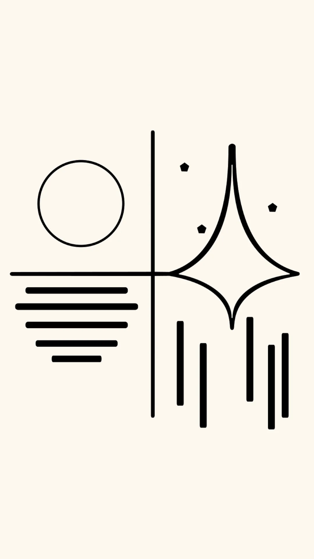
Vector File
To personalize the stand, I created a simple pattern using Inkscape — awesome open source vector software — and exported it as a DXF file. This pattern consisted of multiple closed loops and lines—essential for extrusion later.
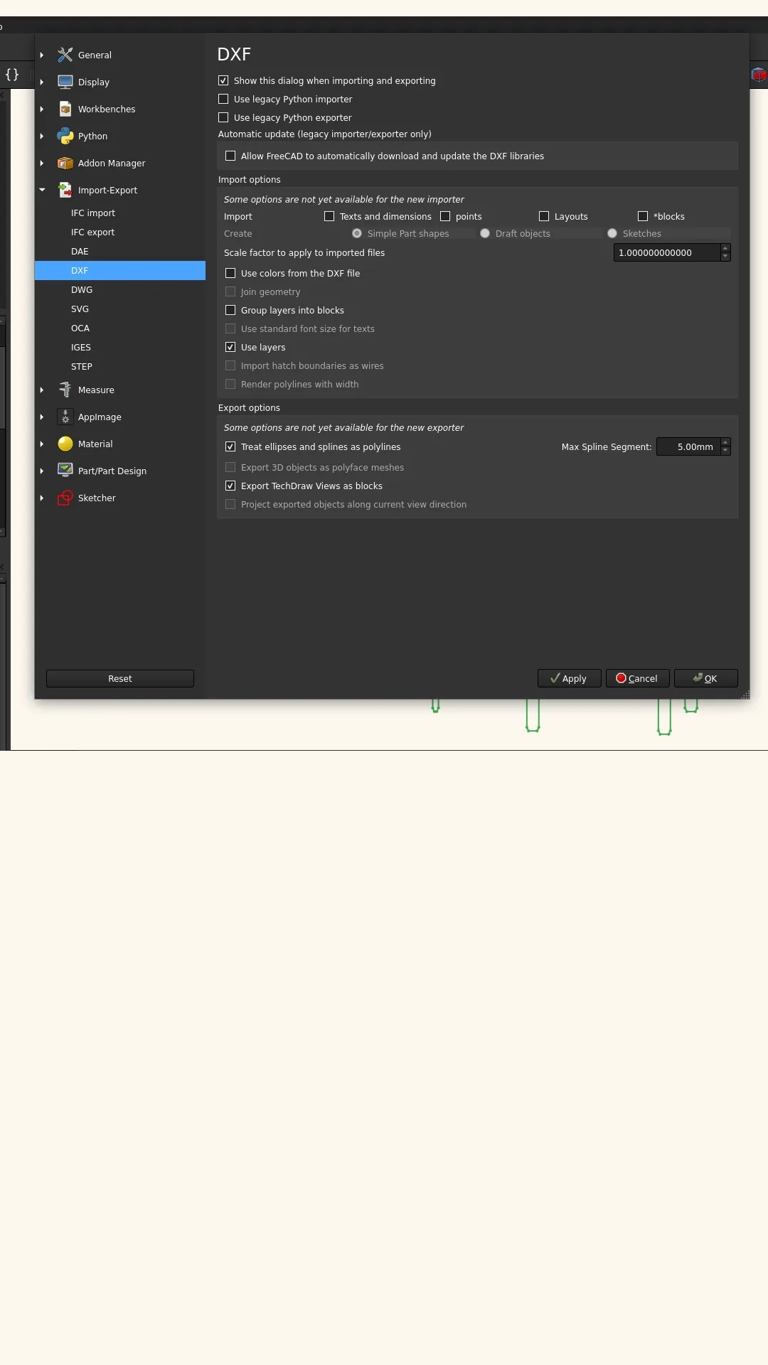
During the import, I modified some settings to bring the vector file as a set of closed sketches. Please feel free to check the settings in the photo.
In FreeCAD: 1. I imported the DXF. 2. Used the Upgrade tool in the Draft workbench to convert polylines to faces. 3. Converted the compound into a usable sketch. 4. Verified all loops were fully closed. Open loops will not work properly.

1. Selected a face for the vector file. 2. Selected the Curves workbench. If you are missing the workbench. Click Tools > Add-on Manager and search for Curves. Click Install. 3. With Curves bench selected, clicked on Sketch on Surface. 4. A blue dashed outline appeared on the top plane. The outline represents the face of the object. 5. Went into an edit mode of the imported sketch, selected entire sketch, CTRL-C and existed the sketch. 6. Opened the Mapped_Sketch and CTRL-V. You may need to rotate the sketch to for proper orientation.
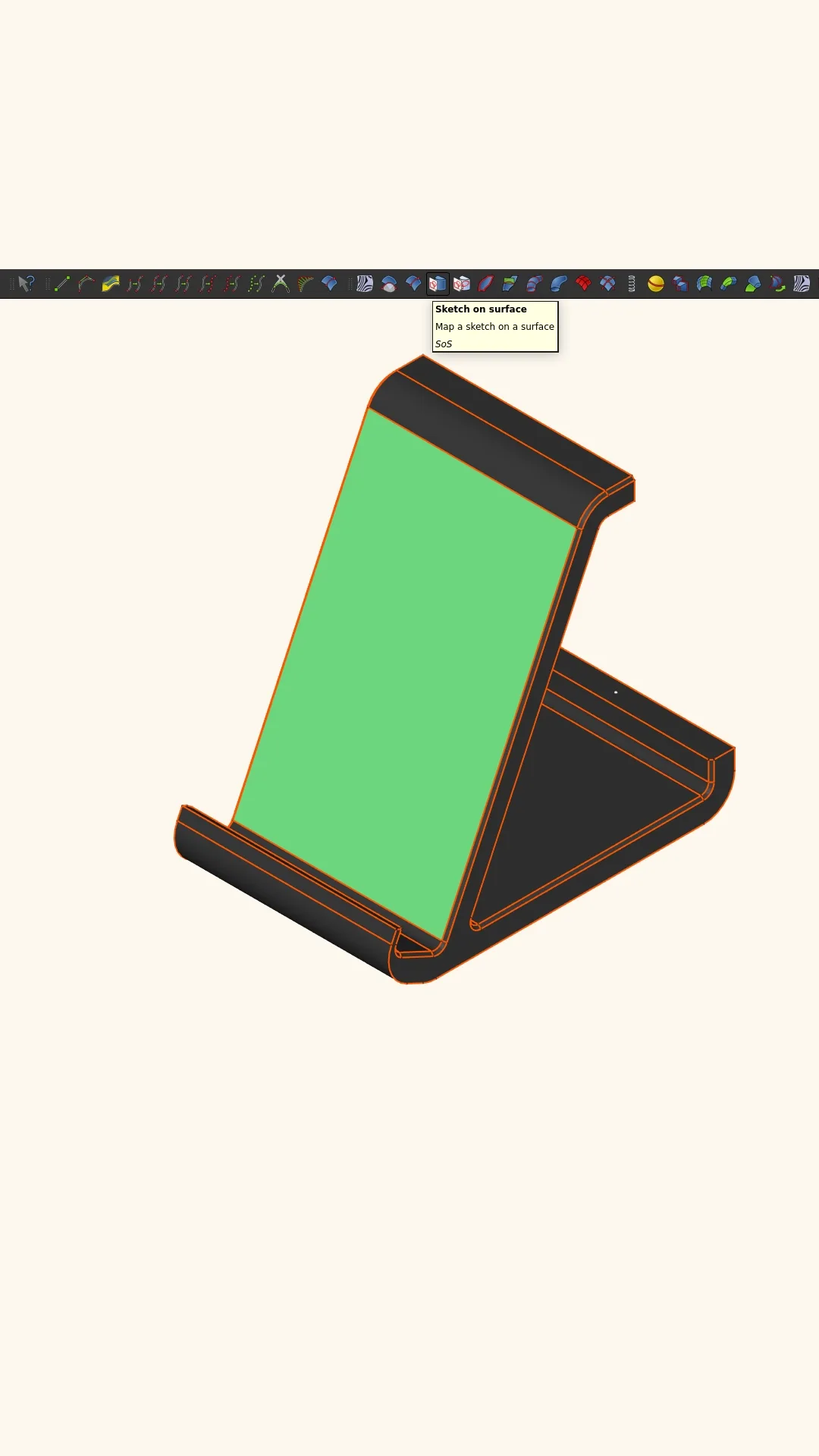
Result - a flat surface on top of the face selected earlier. 7. Offset the surface into the model by -0.4mm 8. Change Fill Extrusions to True 9. Add thickness of 2mm 10. With Part workbench selected, selected part body then Sketch_On_Face and clicked Cut to cut one shape away from the body. *Order of selection is important*
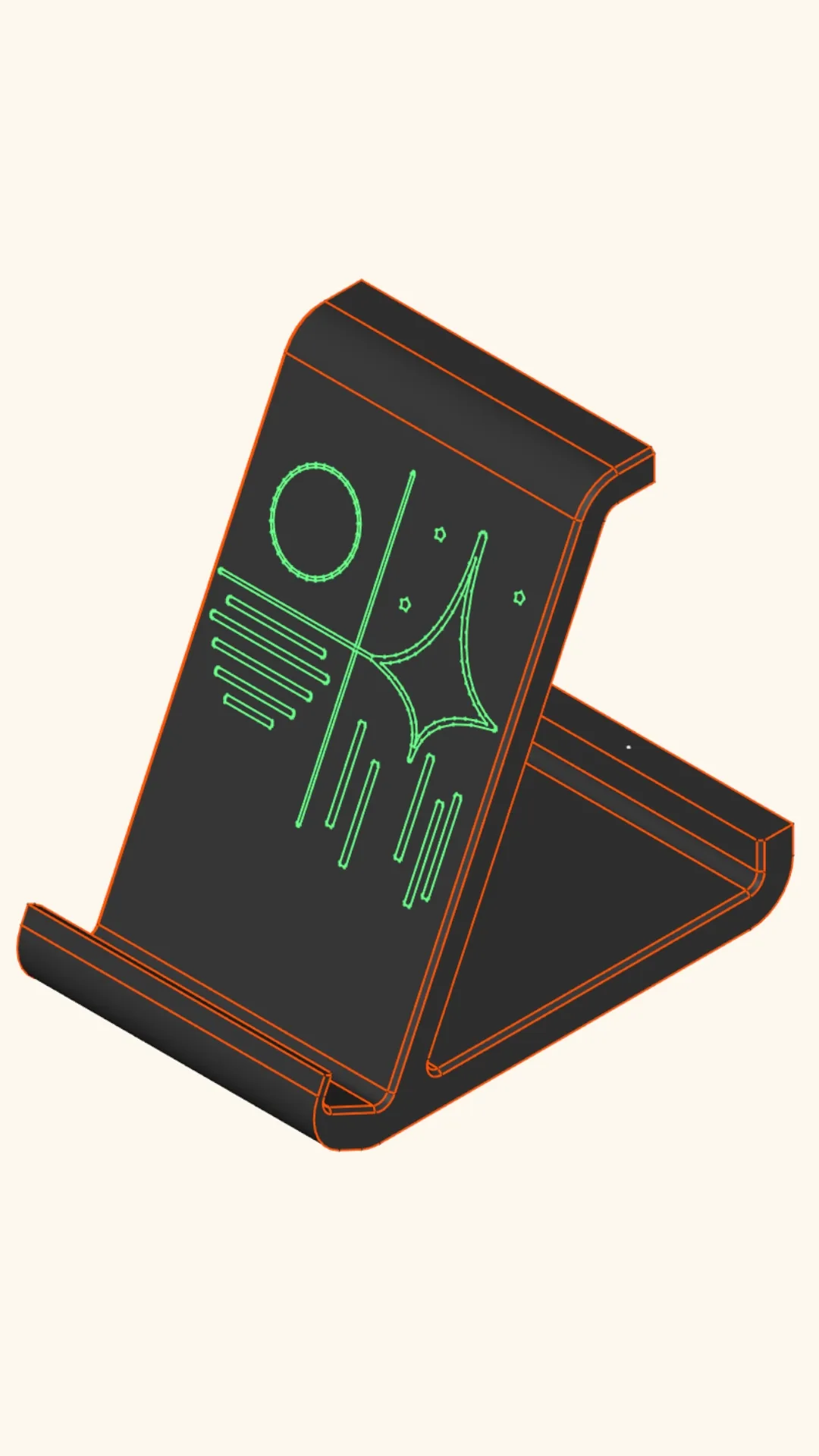
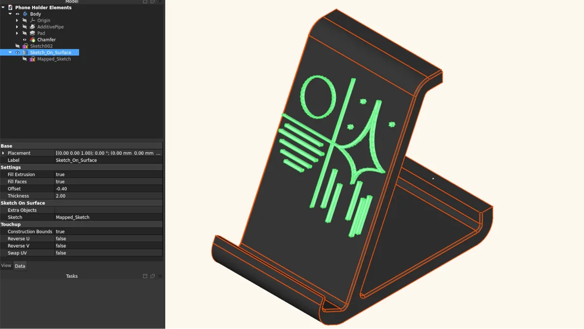
Surface turned to extruded shape
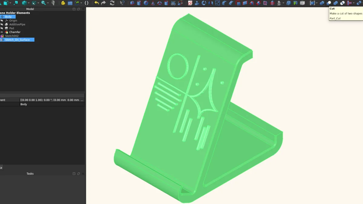
Cutting shape from the body
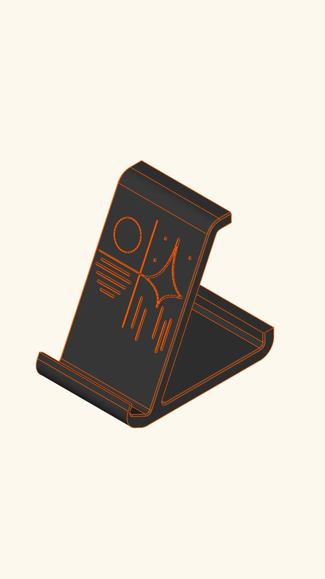
With the model complete, I exported it as a STEP file and imported it into Orca Slicer. 1. Orientation: Printed on its side for better support 2. Printer: Bambu Lab (tested with flexible and rigid materials) 3. Result: Pattern is cleanly engraved; part prints without supports
Final Thoughts This project combines basic sketching, profile extrusion, and custom detailing into a simple but polished design. The resulting phone stand is both useful and visually personal. If you're looking to move beyond plain 3D-printed parts and start adding your own flair, this is a great part to practice. The ability to import DXF designs opens up creative options, from logos to illustrations. As always, thanks for following along. I hope this gives you ideas for your own custom projects.

Comments (0)
No comments yet. Be the first to share your thoughts!